The Only Land Measuring Tool Guide You Need
If you’re looking to understand how a land measuring tool works and why it’s essential for accurate area and boundary calculations, this content explores every major aspect of land measurement. From traditional instruments like measuring tapes and surveyor chains to advanced technologies such as GPS, total stations, and drone-based systems, each land measuring tool serves a unique purpose in determining distance, elevation, and coordinates with precision. You’ll learn how these tools differ in accuracy, functionality, and cost, along with insights into selecting the right land measuring tool for agricultural, construction, or cadastral applications. It also explains how environmental factors, calibration, and operator skill affect measurements, ensuring reliable and legally accepted land data.
What is a land measuring tool?
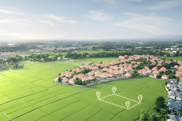
A land measuring tool is any instrument, device, software, or system used to determine distances, angles, areas, and coordinates on the ground. Land measuring tools range from simple handheld tape measures and surveyor chains to sophisticated GNSS/RTK receivers, total stations, drones with photogrammetry or LiDAR, and mobile apps that estimate area from satellite imagery. Each tool has a specific accuracy envelope, cost profile, and ideal use case.
Why the choice of land measuring tool matters
Choosing the right land measuring tool matters because:
- Different tools give very different accuracies (from ±0.1 m for good GNSS/RTK to ±5–10 m for basic smartphone estimates).
- Legal and cadastral work usually requires certified accuracy and traceable procedures.
- Time, cost and logistics vary enormously—manual tools are cheap but slow, drones and GNSS are faster but costlier.
- Post-processing and deliverables change with the tool (paper sketch vs. georeferenced CAD file vs. GIS-ready shapefile).
Categories of land measuring tools (overview)
- Manual distance measures
- Tape measure (steel/fiberglass)
- Surveyor chain (Gunter’s chain, metric chains)
- Odometer (measuring wheel)
- Optical & electro-optical instruments
- Theodolite (angles)
- Total station (angles + electronic distance measurement)
- Laser distance meter (handheld)
- GNSS / GPS systems
- Single-frequency GNSS receivers (consumer)
- Dual-frequency GNSS (survey-grade)
- RTK (Real-Time Kinematic) and PPK (Post Processed Kinematic)
- Remote sensing & photogrammetry
- UAV (drone) photogrammetry (structure-from-motion)
- Drone LiDAR
- Mobile & web applications
- Smartphone apps (area estimator with phone GPS)
- Web-based mapping tools (satellite-drawn area)
- Specialized instruments
- Total stations integrated with robotic heads
- Laser scanners (terrestrial LiDAR)
- GNSS + IMU integrated systems for mapping corridors
How each land measuring tool works — technical deep dive
Tape measure and survey chain
- How it works: Direct physical measurement. A tape (steel or fiberglass) is stretched along a line and length is read.
- Accuracy: Typical ±1–5 mm for steel tapes over short distances, but human error grows with length and alignment.
- Best use: Small parcels, building layouts, fence lines, verification checks.
- Limitations: Not practical for long distances or rough terrain. Thermal expansion of metal tapes affects accuracy; sag and slope must be corrected.
Measuring wheel (odometer)
- How it works: Wheel rotation counts are converted to distance using circumference. Good for rough, long paths.
- Accuracy: ±0.5% to ±2% depending on wheel slip and terrain.
- Best use: Roadside lengths, rough perimeter checks.
- Limitations: Poor on soft, uneven ground; not suited for precise area measurement alone.
Laser distance meters
- How it works: An infrared laser pulse is emitted and time-of-flight or phase shift is used to compute distance.
- Accuracy: Sub-cm to a few mm on short distances; up to ±1–3 cm over tens to hundreds of meters depending on model.
- Best use: Quick point-to-point distances, building interiors, combining with a compass/clinometer for slope distances.
- Limitations: Line-of-sight required; reflective surfaces perform best.
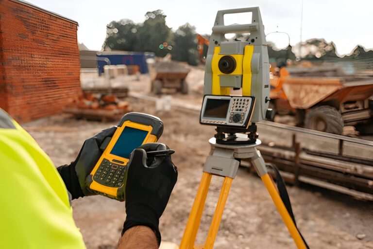
Theodolite and total station
- How it works: Theodolite measures angles (vertical/horizontal). A total station integrates angle measurement with Electronic Distance Measurement (EDM) to compute coordinates.
- Accuracy: Survey-grade total stations can achieve angular accuracy of 1″ (one arc-second) to 5″ and distance accuracy ±(1–3) mm + 1 ppm (parts per million).
- Best use: Precise cadastral surveys, construction staking, control network surveys.
- Limitations: Requires skilled operator, setup time, and stable instrument station.
GNSS / RTK / PPK systems
- How it works: GNSS receivers use satellites (GPS, GLONASS, Galileo, BeiDou). RTK uses a base station and rover to correct real-time carrier-phase measurements; PPK applies corrections in post-processing.
- Accuracy: RTK/PPK can deliver centimeter-level horizontal accuracy and decent vertical accuracy if properly processed.
- Best use: Land parcel mapping, large-area surveys, topographic mapping, where line-of-sight is obstructed (vegetation is fine).
- Limitations: Requires good satellite geometry, base station or network access, multipath and canopy can degrade signals. Vertical errors larger than horizontal if not carefully processed.
Drone photogrammetry (SfM) and LiDAR
- How it works (photogrammetry): Overlapping aerial photos are processed using Structure-from-Motion to produce orthomosaics and DEMs. Ground Control Points (GCPs) or RTK/PPK enable georeferencing.
- How it works (LiDAR): Laser pulses measure direct distances to ground returns—works well under sparse vegetation.
- Accuracy: With good GCPs or RTK-enabled drones, horizontal accuracy can be from 2–10 cm, vertical accuracy depends but often 5–20 cm for photogrammetry; LiDAR can do better under certain conditions.
- Best use: Topographic mapping, large parcel measurement, 3D modeling, inaccessible terrain.
- Limitations: Weather dependent; processing requires computing power; initial cost and regulatory compliance for drone operations.
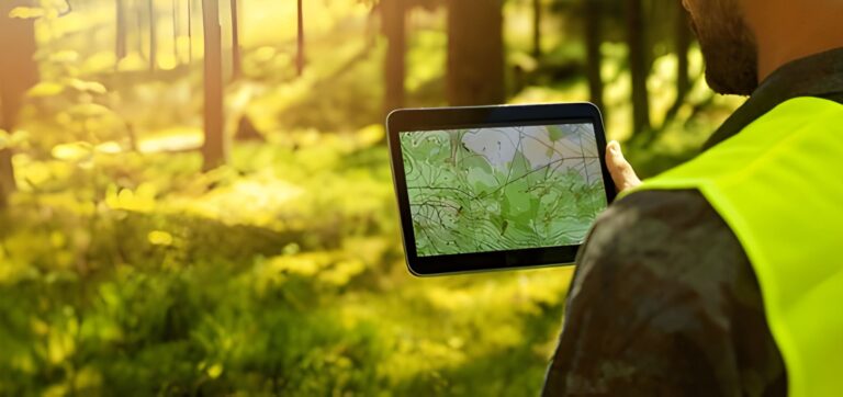
Smartphone apps & web mapping tools
- How it works: Use phone GPS and/or drawing on satellite imagery to estimate area.
- Accuracy: Consumer GPS on phones ±3–10 m commonly; areas derived from satellite imagery depend on resolution—good for rough estimates only.
- Best use: Quick on-site checks, sketching, early-stage estimates.
- Limitations: Not legally acceptable for cadastral work; variable accuracy.
Choosing the right land measuring tool — decision factors
- Required accuracy
- Legal cadastral survey: survey-grade total station or GNSS-RTK with certified procedures.
- Construction layout: total station or RTK GNSS.
- Agricultural or general-purpose area measure: drone photogrammetry, GNSS, or smartphone app depending on tolerance.
- Quick fence-line or garden measurement: tape measure or measuring wheel.
- Plot size and terrain
- Small, flat: tape, laser.
- Large, open: GNSS/RTK, drone.
- Dense vegetation or canopy: LiDAR or total station with line-of-sight where possible.
- Budget
- <$200: measuring wheel, tape, consumer laser.
- $1k–5k: decent GNSS rover, professional laser.
- $10k–50k+: survey-grade GNSS/RTK, total stations, LiDAR systems.
- Skill level
- Simple tools: minimal skill.
- Total station, GNSS RTK, drone photogrammetry: requires training, permits, and practice.
- Deliverables required
- Paper sketch vs. CAD plan vs. georeferenced GIS file: choose a tool that outputs desired formats or can be post-processed into them.
Step-by-step: how to measure a land parcel (practical workflow)
Below is a robust workflow suitable for many projects. I’ll show two workflows — one low-tech (tape/laser + hand-drawn area) and one high-accuracy (GNSS/RTK or total station).
Low-tech workflow (small parcel, no legal requirement)
- Prepare: Bring tape (50 m), laser distance meter, compass, notebook, pen, and camera.
- Sketch: Draw a rough sketch of the parcel with boundary markers labeled (A, B, C, D…).
- Measure sides: Measure each boundary length using tape or laser. For slopes, measure slope distance and record slope angle to compute horizontal projection.
- If slope distance
smeasured and slope angleθ:- Horizontal distance
h = s × cos(θ). - Vertical difference
v = s × sin(θ).
- Horizontal distance
- Compute carefully: example — if s = 12.00 m, θ = 15°, cos(15°)=0.965925826, h = 12.00 × 0.965925826 = 11.591109912 → round appropriately.
- If slope distance
- Measure diagonals: For reliability, measure at least one diagonal in quadrilaterals.
- Compute area:
- For regular shapes: use geometric formulas (rectangle length × width).
- For polygons: break into triangles or use the shoelace formula.
- Shoelace formula (for coordinates) gives accurate area from vertex coordinates.
- Record landmarks and photos: Take photos of corner markers and nearby fixed objects for reference.
High-accuracy workflow (legal, cadastral, or large areas)
- Planning:
- Check title/deed and existing cadastral coordinates if available.
- Plan control network: place stable ground control points (GCPs).
- Establish control:
- Use a survey-grade GNSS base station over a known point or set up a temporary base with known coordinates. Or use a continuous GNSS network (CORS).
- Data collection:
- For GNSS-RTK: rover collects points at boundary corners using centimeter-level observation methods (occupy pole, record number of satellites, PDOP, observation time).
- For total station: set up instrument over a station, measure angles and distances to reflectors at boundary corners.
- For drone mapping: fly planned mission ensuring 70–80% forward overlap and 60–80% side overlap; mark and measure GCPs accurately.
- Quality control:
- Check closure errors for polylines and loop closures. For GNSS, check baseline vector residuals.
- Re-observe suspicious points.
- Processing:
- Apply RTK corrections, or process raw GNSS data via PPK, or process total station raw readings to produce coordinates.
- For photogrammetry: process images with SfM software and tie to GCPs.
- Compile deliverables:
- Produce plan drawings (CAD), coordinate table (CSV), shapefiles, and legal descriptions as needed.
Area computation methods (technical details)
Shoelace formula (polygon area from coordinates)
Given polygon vertices (x₁,y₁), (x₂,y₂), …, (xₙ,yₙ) in order, area A is:
A = 0.5 × | Σ (xᵢ × yᵢ₊₁ − xᵢ₊₁ × yᵢ) |, where (xₙ₊₁,yₙ₊₁) = (x₁,y₁).
This formula is robust and used when inputting coordinates from GNSS or total station.
Triangle decomposition
Break a polygon into non-overlapping triangles from a reference vertex, compute each triangle area using base×height or Heron’s formula, and sum.
GPS polygon area calculation (on ellipsoid)
When coordinates are in lat/long, use geodetic area algorithms (e.g., geodesic polygon area using ellipsoid model) implemented in GIS software — necessary for large parcels spanning significant latitudinal extent.
Land Measurement Standards, Units, and Coordinate Systems
Accurate land measurement is not only about collecting data—it also depends on using standardized units, reference systems, and coordinate frameworks to ensure consistency and legal acceptance.
Measurement units vary by region and application. Most professional surveys use metric units (meters and square meters), while some regions still rely on feet, acres, or local traditional units. Conversions must be handled carefully to avoid scale errors in area calculations.
Coordinate systems define how measured points are represented. Local surveys often use projected coordinate systems (such as UTM or national grid systems) that preserve distance and area accuracy. Global datasets and GNSS receivers typically use geographic coordinates (latitude and longitude) based on global datums like WGS84.
Map projections matter when calculating area over large regions. Using raw latitude-longitude values without a proper projection can lead to distorted area results, especially over long distances or varying latitudes. Professional GIS and surveying software apply appropriate projections before computing area.
Survey standards and tolerances are defined by local authorities and professional bodies. These standards specify acceptable closure errors, observation procedures, documentation requirements, and instrument accuracy classes. Compliance ensures that results are repeatable, defensible, and legally valid.
By adhering to recognized units, coordinate systems, and standards, land measurement data becomes interoperable across CAD, GIS, legal records, and engineering workflows—reducing disputes and improving long-term data reliability.
Accuracy, precision, and error sources
Typical accuracy by tool
- Tape measure (short): ±0.005–0.01 m (very small distances).
- Laser meter: ±0.001–0.02 m depending on model and distance.
- Total station: ±(1–3) mm + 1 ppm in distance; angular accuracy 1–5″.
- GNSS RTK/PPK: horizontal ±1–3 cm typical; vertical usually ±2–10 cm.
- Drone photogrammetry (with GCPs): horizontal 2–10 cm; vertical 5–30 cm typical.
- Smartphone GPS: ±3–10 m (consumer).
Common error sources
- Measurement device precision limits.
- Human errors in setup, reading, marking.
- Thermal expansion of metal tapes.
- Slope and not correcting to horizontal.
- Multipath and signal blockage for GNSS.
- Poor overlap or motion blur in drone imagery.
- Incorrectly placed or measured Ground Control Points.
Environmental Factors That Impact Land Measurement Accuracy
Environmental conditions play a significant role in the accuracy and reliability of any land measuring tool. Even survey-grade instruments can produce biased results if external factors are not properly accounted for.
Temperature and atmospheric conditions affect measurements directly. Steel tapes expand with heat, while electronic distance measurement (EDM) instruments are influenced by air temperature, pressure, and humidity. These variables change the speed of light in air, which is why professional instruments apply atmospheric corrections.
Terrain and slope also introduce errors. Measurements taken on sloping ground must be reduced to horizontal distance; failure to do so can significantly overestimate parcel size. Uneven surfaces further increase alignment and setup errors, especially for manual tools.
Vegetation and obstructions impact both optical and satellite-based systems. Total stations require clear line-of-sight, while GNSS accuracy degrades under dense tree canopy due to signal blockage and multipath reflections. LiDAR performs better in such environments but is not immune to noise from thick foliage.
Weather conditions such as wind, rain, fog, and dust affect visibility, drone stability, and instrument setup. Strong winds can tilt survey poles or disturb drones, while rain and fog reduce laser and optical performance.
Satellite geometry and signal environment are critical for GNSS measurements. Poor satellite distribution (high PDOP), nearby buildings, metal objects, or reflective surfaces can distort signals and reduce positioning accuracy.
Understanding and documenting these environmental factors helps surveyors choose the correct land measuring tool, apply necessary corrections, and justify data quality in professional or legal contexts.
Calibration, maintenance and best practices
- Tape and chain: Keep stored dry, check for kinks, calibrate length against a certified baseline periodically.
- Total station: Regularly calibrate angular encoders, check collimation, and perform EDM checks per manufacturer schedule.
- GNSS receivers: Update firmware, antenna mounting checked, ensure logging settings are correct.
- Laser meters: Clean optics, ensure battery levels are good, test against a known distance.
- Drones: Calibrate IMU, compass; perform pre-flight checks; ensure camera focus and exposure stable.
- General: Keep a calibration logbook and record calibration dates for legal audits.
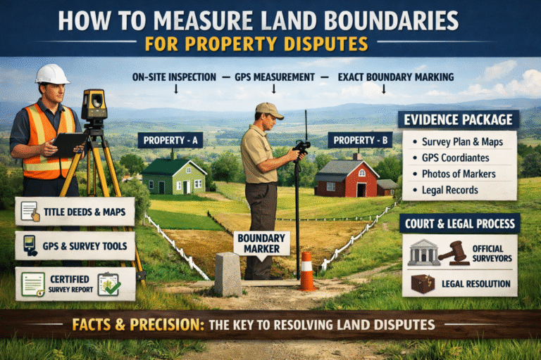
Legal and cadastral considerations
- Many jurisdictions require licensed surveyors for cadastral or boundary surveys—always check local laws before performing surveys meant for legal purposes.
- Records must be traceable: field notes, coordinate files, instrument serial numbers, calibrations, and operator signatures may be required.
- Use certified equipment for official surveys and follow standards (local surveying standards or ISO where applicable).
- For drone surveys, comply with aviation regulations and data privacy rules about capturing images of people/private property.
Data formats and deliverables
Typical digital deliverables from a land measuring tool workflow:
- CSV or TXT point lists (X, Y, Z)
- DXF/DWG CAD files (parcels, boundaries)
- Shapefiles or GeoPackage for GIS
- GeoTIFF orthomosaic and DEM from drone photogrammetry
- PDF survey plan with legal description
- RINEX or raw GNSS observation files (if needed for post-processing)
Common practical scenarios — recommended land measuring tool
- Small urban plot, legal boundary needed: Survey-grade GNSS RTK or total station (depends on line-of-sight). Deliver CAD + coordinates.
- Large agricultural field for area and volume: Drone photogrammetry with GCPs or GNSS area walk with rover—drone preferred for speed.
- Road or linear corridor: GNSS RTK with mobile mapping or LiDAR-equipped vehicle.
- Rough terrain with dense trees: LiDAR (drone or terrestrial) or total station where access allows.
- Quick backyard estimate: Smartphone app or measuring wheel for rough area.
Checklist before using any land measuring tool (quick reference)
- Define required accuracy and deliverables.
- Check legal requirements for certified survey.
- Select appropriate instrument and backup instruments.
- Verify batteries, memory, and backups.
- Place or plan control points (GCPs or control stations).
- Record environmental conditions (weather, canopy cover, satellite availability).
- Note instrument model and serial, and operator name in field book.
- Do multiple observations for quality control.
Common mistakes and how to avoid them
- Not correcting for slope: Always convert slope distance to horizontal when necessary.
- Poor closure checks: For polygon loops, compute closure error and make sure it’s within tolerance; remeasure if not.
- Assuming phone GPS is survey-grade: Use phone-only data for preliminary, not legal, purposes.
- Skipping calibration: Instrument drift causes systematic errors; calibrate.
- No backup: Always take redundant measurements (e.g., measure a diagonal).
Example: calculating area using shoelace (worked example)
Suppose you measured four points (a quadrilateral) using a GNSS or total station and got these coordinates in meters (projected coordinate system):
Point A: (1000.00, 2000.00)
Point B: (1010.00, 2005.00)
Point C: (1012.00, 1995.00)
Point D: (1002.00, 1990.00)
Apply the shoelace formula:
- Write coordinates in order and repeat first at end.
- (1000.00, 2000.00)
- (1010.00, 2005.00)
- (1012.00, 1995.00)
- (1002.00, 1990.00)
- (1000.00, 2000.00)
- Compute Σ(xᵢ × yᵢ₊₁):
- 1000.00 × 2005.00 = 2,005,000.00
- 1010.00 × 1995.00 = 2,015, – compute carefully: 1010 × 1995 = 1010×2000 − 1010×5 = 2,020,000 − 5,050 = 2,014,950.00
- 1012.00 × 1990.00 = 1012×1990 = 1012×2000 − 1012×10 = 2,024,000 − 10,120 = 2,013,880.00
- 1002.00 × 2000.00 = 2,004,000.00
- Sum = 2,005,000 + 2,014,950 + 2,013,880 + 2,004,000 = 8,037,830.00
- Compute Σ(xᵢ₊₁ × yᵢ):
- 1010.00 × 2000.00 = 2,020,000.00
- 1012.00 × 2005.00 = 1012×2005 = 1012×2000 + 1012×5 = 2,024,000 + 5,060 = 2,029,060.00
- 1002.00 × 1995.00 = 1002×1995 = 1002×2000 − 1002×5 = 2,004,000 − 5,010 = 1,998,990.00
- 1000.00 × 1990.00 = 1,990,000.00
- Sum = 2,020,000 + 2,029,060 + 1,998,990 + 1,990,000 = 8,038,050.00
- Subtract and take half absolute:
- Difference = 8,037,830.00 − 8,038,050.00 = −220.00
- Absolute = 220.00
- Area = 0.5 × 220.00 = 110.00 square meters.
So the parcel area is 110.00 m². (This worked example shows the exact arithmetic steps used to avoid mistakes.)
Final recommendations & buying guide (which land measuring tool for you)
- Homeowner, occasional use, small budget: Laser distance meter + tape measure. Easy to learn, accurate for small tasks.
- Small surveying business, mixed jobs: Mid-range GNSS dual-frequency rover with base or subscription to an RTK network. Add a total station for construction staking.
- Large parcels, fast delivery: Drone with RTK/PPK integration and photogrammetry workflow, or GNSS RTK rover depending on vegetation cover.
- Cadastral, legal surveys: Survey-grade total station or GNSS RTK, with certified procedures and local licensed surveyor involvement.
- Vegetated or complex terrain: LiDAR (drone or terrestrial) combined with photogrammetry where needed.
Conclusion
A land measuring tool is not one-size-fits-all. The right choice depends on required accuracy, terrain, budget, legal requirements, and deliverables. This guide covered the physics and principles behind major tools, detailed workflows for both quick and high-accuracy surveys, computation methods (including a worked shoelace example), calibration and legal considerations, and practical recommendations.
Image Credit: Shutter Stocks